
Structural Design and Detailing
Steel Detailing
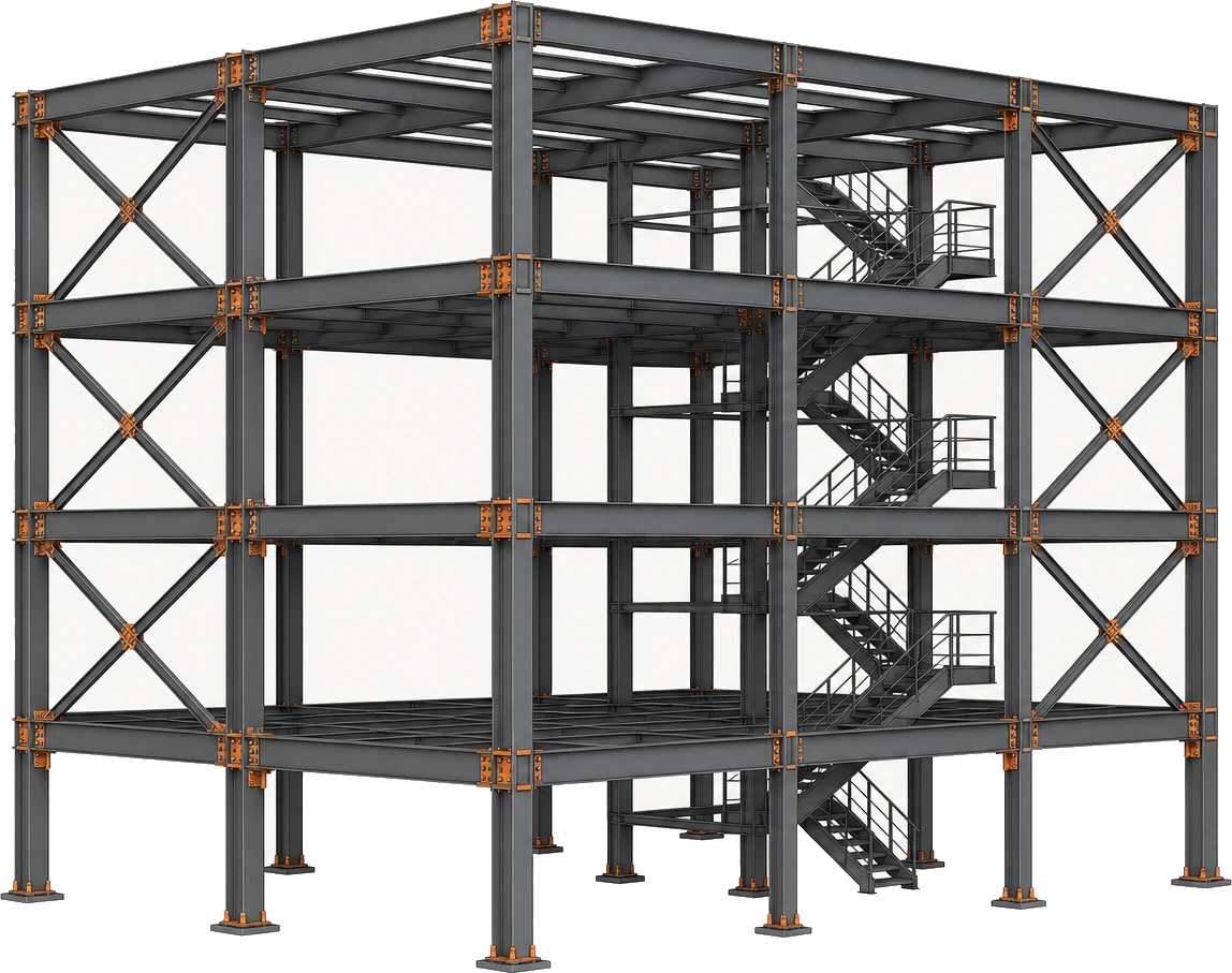
Structural design drawings turned into a coordinated 3D steel model and the drawings a shop and a crew build from: general arrangement, erection plans, assembly and single part drawings, anchor bolt layouts, and matching material lists.
Steel detailing
Services we cover
Column Schedules Beam Details Bracing Layouts Base Plate Details Stair & Handrail Details Platform & Mezzanine Framing Miscellaneous Metals Roof Framing Plans
Moment Connections Shear Connections Gusset Plate Details Splice Details Embed & Anchor Assemblies Truss Detailing Canopy & Awning Framing Crane Beam Details
Overview
What is Steel Detailing?
Steel detailing is the step between a structural engineer's design and a fabricated, erected steel frame. The design drawings say what the structure has to do: member sizes, grades, loads, and connection criteria. Detailing works out the rest. It gives each beam its length and copes, each plate its thickness and hole pattern, each bolt its diameter, grade, and position, and each piece a mark it carries through the shop and onto the site.
The work is done in a 3D model. Columns, beams, braces, trusses, stairs, handrails, and platforms are modeled in place, connections are built on them, and clashes are resolved before anything is cut. The drawings, piece marks, material lists, and machine files all come out of that one model, so they agree with each other without manual cross checking.
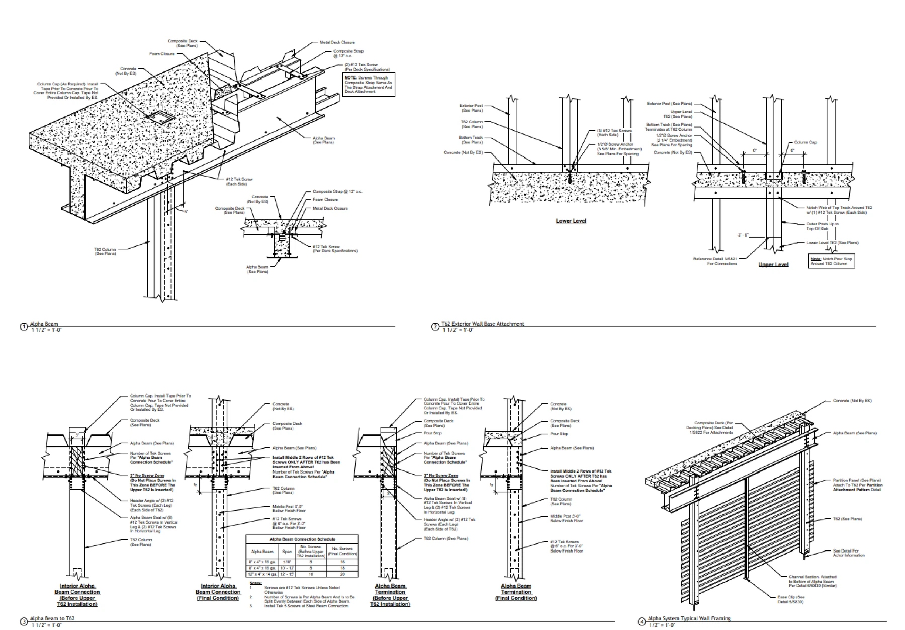
The output is a package two audiences can work from. The fabricator gets single part and assembly drawings with the cuts, holes, bevels, and welds spelled out. The erector gets general arrangement and erection drawings that show where each marked piece lands, what bolts it, and in what order the frame goes up.
What we deliver
What's included in a Steel Detailing package
Every deliverable comes from the same detailing model and shares one set of marks and one bill of material. Each one is checked against your structural drawings before it is issued for approval.
-
3D Detailing Model
The full frame modeled in place: columns, beams, braces, trusses, stairs, and platforms, with connections built on the members.
-
General Arrangement Drawings
Framing plans, elevations, and sections that show the whole structure with grids, levels, and member sizes.
-
Erection Drawings
Piece marks placed on the frame with field bolts, field welds, and the notes the crew needs to set steel in sequence.
-
Assembly Drawings
Shop welded assemblies drawn as one piece, with the attached plates, stiffeners, and welds dimensioned.
-
Single Part Drawings
Individual members and plates with lengths, copes, bevels, hole sizes, and gauge lines ready for the shop floor.
-
Anchor Bolt Setting Plans
Anchor rod layouts, projections, and base plate positions dimensioned off the grid so the concrete crew can set them early.
-
Material Lists & CNC Data
Advance bills of material, shipping lists, and NC or DSTV files exported to suit the machines your shop runs.
Where the detail lives
Connections we detail
A steel frame depends on the joints between its members. These are the connection types that make up most of a job, with what each one does and what you get for it.
Shear Connections
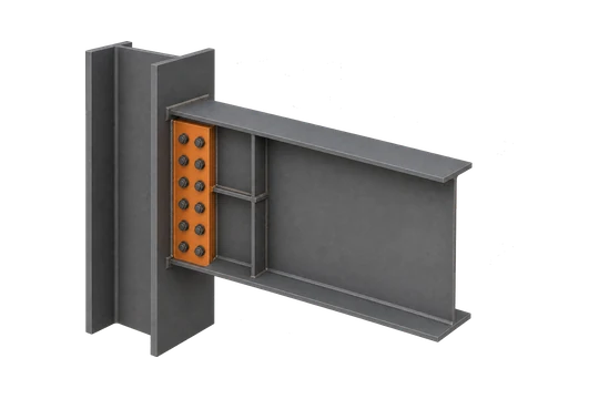
The everyday simple connection that carries a beam reaction into a girder or column without holding moment. Shear tabs, clip angles, and end plates.
You getBolt group layout, gauge lines and edge distances, cope dimensions, and the plate cut on the single part drawing.
Moment Connections
A rigid joint that transfers bending as well as shear, used where the frame resists lateral load without bracing. Flange plates, direct welds, or bolted end plates.
You getFlange and web details, weld symbols and preparation, continuity plates and doubler plates modeled on the column.
Base Plates
Where the column lands on the foundation and hands its load to the concrete. Plate, welds, anchor rods, and the grout space underneath.
You getPlate size and thickness, hole pattern, weld detail, plus the anchor bolt setting plan the concrete crew works from.
Bracing & Gusset Plates
The diagonal members that keep the frame stable, and the gusset that gathers the brace, beam, and column work points into one joint.
You getWork point geometry, gusset shape and thickness, brace end details, and bolt or weld capacity laid out to the design.
Beam Splices
A joint that continues a beam or girder past a shipping length or a change of section, keeping the member acting as one piece.
You getFlange and web splice plates, bolt layout, fill plates where sections change, and the split marked for shipping.
Embeds & Anchor Assemblies
Plates and rod assemblies cast into concrete so steel can be attached later, at slab edges, walls, and pits.
You getEmbed plate details with headed studs or rebar anchors, setting dimensions, and a separate list for the early concrete pour.
Why it matters
Why is Steel Detailing necessary?
Structural drawings are not buildable on their own. They size the members and set the criteria, but they do not tell a saw where to cut, a drill line where to punch, or a crane crew which piece goes up first. Detailing supplies that missing layer, and it is the last chance to catch a problem while it is still cheap to fix.
Once steel is cut, mistakes are hard to undo. A hole in the wrong place or a member two inches too long has to be scrapped or fixed in the field, and the job waits. Resolving the frame in a model first catches those errors on screen, before the steel is on a truck.
-
It turns design intent into exact cut lengths, hole positions, and weld sizes the shop can work to without interpreting anything.
-
Modeling the whole frame exposes clashes, missing members, and impossible joints before material is ordered.
-
Piece marks give every member one identity that carries from the shop through the truck to the exact spot on the frame.
-
Material lists come straight from the model, so ordering, nesting, and shipping quantities match what is actually drawn.
-
The same model feeds the machines, which cuts manual data entry and the transcription errors that come with it.
-
Erection drawings give the crew a clear sequence and bolt list, so steel goes up faster and safer with fewer field decisions.
Where it applies
Industries We Serve
-
01
Steel Fabricators
Detailing capacity that matches your shop standards, machine data needs, and shipping limits.
-
02
Structural Engineers
Detailing that follows your design and comes back organized for a quick approval review.
-
03
Steel Erectors
Erection drawings and marked frames that make sequencing, bolting, and field work straightforward.
-
04
General Contractors
Coordinated steel packages that keep the concrete, steel, and follow-on trades in step.
-
05
Industrial & Plant
Pipe racks, equipment supports, access platforms, and heavy framing detailed for plant sites.
-
06
Commercial & Institutional
Multi-story frames, long span roofs, and canopies for offices, schools, retail, and healthcare.
-
07
Miscellaneous Metals
Stairs, handrails, ladders, grating, and support steel detailed alongside the main frame.
How it works
Our End-to-End Process
01
Review the Design
We read the structural drawings and specification, log queries, and agree on the standards and marking rules.
02
Model the Frame
Columns, beams, braces, and secondary steel are modeled to grid and level, then checked for fit.
03
Detail the Connections
Every joint is built on the model to the engineer's design and your shop standards.
04
Check & Submit
Drawings and lists are checked against the design, then issued for approval and revised on comment.
05
Release & Support
We release for fabrication with machine files and stay available through the shop and erection.
Why Arcengine
Why Choose Us
Detailers Who Think Like Fabricators
Drawings laid out the way a shop reads them, with shipping, handling, and fit-up considered before issue.
Detailed in Your Software
We work in the industry standard tools: Tekla Structures, SDS2, Advance Steel, and AutoCAD.
Connection Accuracy
Joints built on the model to the engineer's design, with bolt grades, gauges, and welds resolved piece by piece.
Works to Your Standards
Your title blocks, layer rules, mark numbering, and drawing conventions, followed exactly.
Checked Before It Leaves
An independent checker reviews marks, dimensions, and material lists against the design before every issue.
Confidential & Secure
Your drawings and project data handled securely and privately.
Explore more
Our Other Services
FAQs
Frequently Asked Questions
Steel detailing is the process of turning a structural engineer's design drawings into a coordinated 3D model and the drawing set a fabricator and erector build from. It fixes every member size, cut, hole, weld, and bolt, then issues that information as general arrangement, erection, assembly, and single part drawings with matching material lists.
A typical package includes the 3D detailing model, general arrangement drawings, erection drawings with piece marks, assembly drawings, single part drawings, anchor bolt setting plans, and an advance bill of materials. Machine files for the shop can be issued alongside the drawings.
We detail in the industry standard tools: Tekla Structures, SDS2, Advance Steel, and AutoCAD. We work in whichever of these your fabricator or engineer already uses, and deliver in the formats your team runs.
We detail connections to the design given by your engineer of record. Where a connection is delegated, we model and detail it against the reactions and criteria the engineer issues, and the engineer keeps responsibility for the design and any stamp.
Send the structural drawings, the connection design or reaction schedule, the specification, and any architectural or MEP backgrounds that affect the steel. Your fabricator's shop standards, piece mark rules, and preferred file formats help us match your workflow from the first drawing.
Yes. The detailing model produces NC and DSTV files for beam lines, drill lines, plate cutting, and saws, exported to suit the machines your shop runs. Material lists and nesting information can be issued with them.
Approval comments are taken back into the model so drawings, marks, and material lists stay consistent. Revised sheets are clouded and revision numbered, and we issue a clear list of what changed so the shop and the field can pick up the update.
Yes. We keep all project files and drawings strictly confidential and manage the data securely.
Get in touch
Detailed for the shop, marked for the field
Send your structural drawings and connection design. We will confirm the standards, marking rules, and formats, then return a checked steel detailing package with drawings, material lists, and machine files.