
Construction Drawings
Architectural Construction Drawings
The architectural working drawings a crew builds from: wall types keyed to a partition legend, envelope details that hold water out, circulation drawn to code, and schedules that match the plans.
Overview
What are Architectural Construction Drawings?
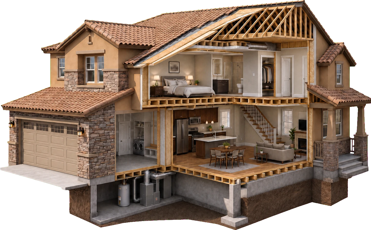
Architectural construction drawings are the working drawings the architectural discipline produces once the design is settled. Design drawings show what the building looks like. These show how it goes together: which wall is which, how the envelope keeps water out, how the stair lands, where a rating runs, and what every door and finish mark refers to. Trades measure and order from them, then build to them.
Resolution is what separates a drawing that reads well from one that builds well. A wall drawn as a plain line leaves the framer to guess its build-up, while a wall with a type mark pointing to a legend answers that on the sheet. We draft to the level where those questions stop coming back from the site, and we keep marks, dimensions, and schedules consistent across every sheet.
On a live job, the architectural drawings are issued alongside the structural and services sheets as part of the full construction document set, so we cross-check our plans and sections against the structural and MEP drawings as they develop. They are also one part of our wider construction drawing service, which covers the interior, millwork, ceiling, and site drawings around them.
At a glance
-
Best for
-
Permit & construction issue sets
-
Covers
-
Plans, elevations, sections, details & schedules
-
Drawn in
-
AutoCAD · Revit
-
Delivery
-
DWG · PDF · RVT
-
Coordinated with
-
Your structural & MEP consultants
What we deliver
What's included in an architectural drawing package
Drawn at build resolution and cross-checked before it leaves us: plans that carry type marks, sections that show the build-up, details where the geometry gets tight, and annotation that reads the same on every sheet.
-
Dimensioned Plans with Type Marks
Level plans on grid, with dimension strings, room names and numbers, and every wall carrying its partition type.
-
Enlarged Plans
Stairs, restrooms, kitchens, and other tight areas drawn at a bigger scale where the main plan runs out of room.
-
Elevations, Inside and Out
Exterior and interior elevations with material extents, opening positions, finish heights, and datum references.
-
Building and Wall Sections
Cuts through the building showing floor-to-floor heights and how each assembly stacks from footing to parapet.
-
Detail Sheets
Enlarged details at junctions, transitions, and terminations, each one keyed back to the section it came from.
-
Legends, Keynotes and Symbols
Partition legend, material keys, symbols, and sheet keynotes so annotation means the same thing everywhere.
-
Keyed Schedules
Door, window, finish, and room schedules whose marks match the plans and elevations exactly.
Drawn to answer
What the architectural set resolves
Every question below gets settled on paper, or it gets settled on site by whoever is holding the tape measure that morning. The architectural drawings are responsible for all six.
Wall types and assemblies
Every wall on plan carries a type mark pointing to a partition legend that fixes the stud, layers, insulation, board, and rating for that mark, so a type drawn once is built the same way everywhere.
The builder getsA defined build-up for every wall in the project.
The building envelope
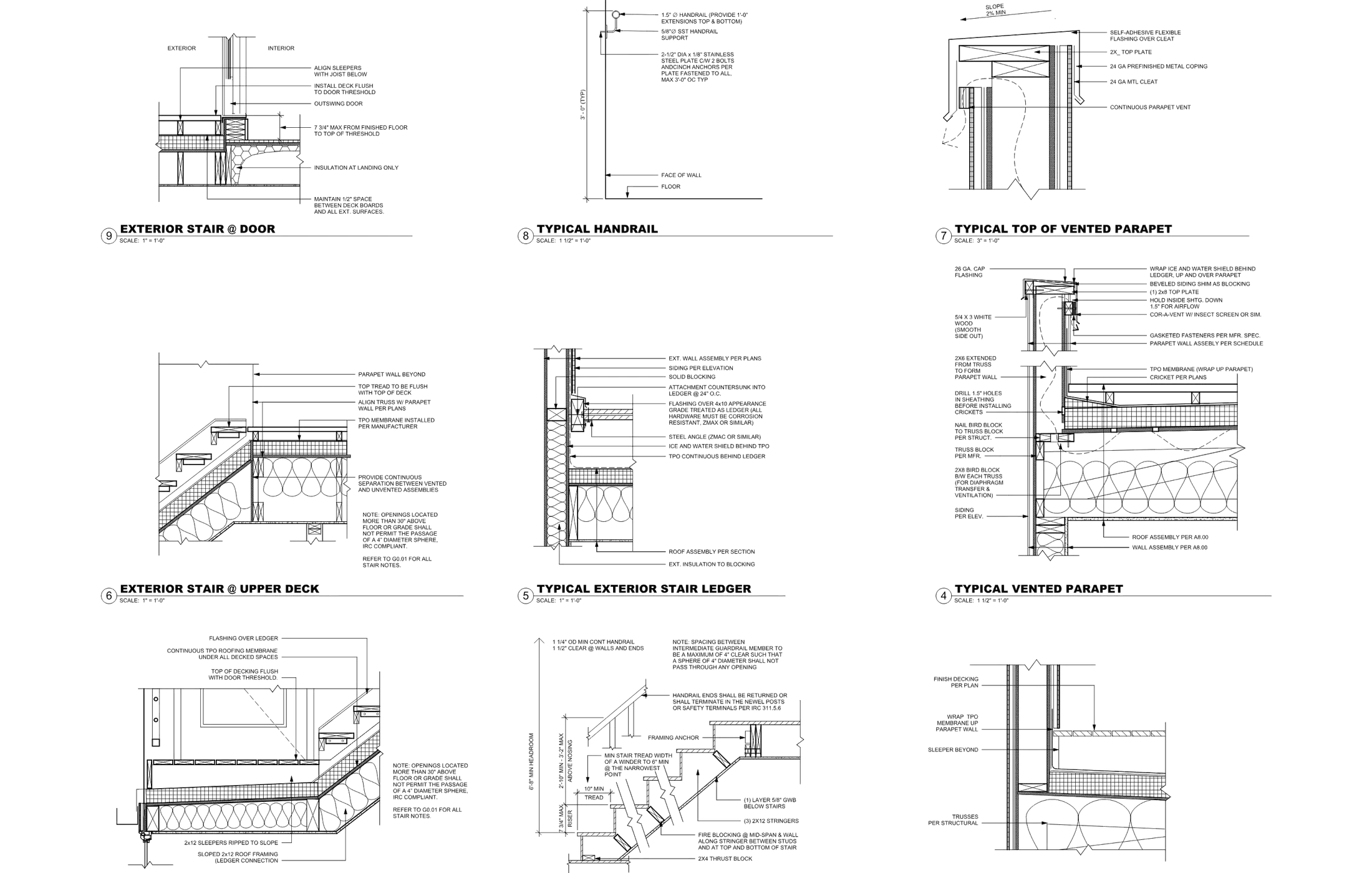
Wall sections through the exterior, plus enlarged details at the places that leak: sills, heads, jambs, base of wall, parapet, and roof edge. Waterproofing, flashing, insulation, and air barrier are drawn as one continuous path.
The builder getsA drawn lap sequence instead of a field decision.
Vertical circulation
Stairs, ramps, and elevator shafts drawn as enlarged plans and sections: riser and tread dimensions, landings, headroom, slope, handrail and guard heights, all resolved to code before framing starts.
The builder getsA stair that fits the opening it was drawn into.
Fire ratings and separations
Rated walls, shafts, and occupancy separations shown as continuous runs with the rating and assembly called out, carried up through the sections so a ceiling change or a penetration does not break them unnoticed.
The builder getsA visible rating line to build to and inspect against.
Accessibility clearances
Accessible route widths, door approach clearances, turning space, counter and fixture heights, and reach ranges dimensioned on the plans, at a scale where they can be checked.
The builder getsClearances that survive framing and fit-out.
Door, window and finish schedules
Every opening and every surface carries a mark that ties back to the plans and elevations, with type, size, material, hardware group, and finish held in one coordinated list.
The builder getsOne list procurement and installation both work from.
Why it matters
Why architectural drawings carry the build
The architectural drawings are the only place the whole building is described as one object. Structural drawings describe what holds it up and services drawings describe what runs through it. The architectural set is where the room dimension, wall build-up, opening, finish, and rating all have to agree at once. When they disagree, the conflict is found on site, where it is expensive to fix.
Most of what slows a job down is a simple question left unanswered: a wall with no type, a detail that stops short of the joint, a schedule mark that is not on any plan. Resolving those up front is the cheapest work on the project.
-
The trades measure from these sheets and lay out the work from their dimensions, levels, and openings.
-
The set fixes the assemblies, so material takeoffs and orders come straight off the drawings.
-
Ratings, egress, and clearances are drawn so an inspector can see and check them.
-
Each detail resolved on paper removes a request for information, and the delay that comes with it.
-
It gives the structural and services teams a stable architectural base to coordinate their own drawings against.
-
The issued set becomes the reference for change orders, handover, and any later as-built record.
Where it applies
Industries We Serve
-
01
Architects & Design Firms
Production capacity that takes a resolved design and draws it out to build resolution, in your templates.
-
02
General Contractors
Drawings detailed enough to lay out from, with the assemblies and clearances already settled.
-
03
Multi-Family & Residential
Repeating unit types drawn once and held consistent, with party wall and shaft ratings carried through.
-
04
Commercial & Mixed-Use
Office, retail, and mixed-use where core, shell, and tenant areas each need their own level of resolution.
-
05
Healthcare & Education
Rating-heavy, clearance-heavy buildings where the separations and accessible routes have to read clearly.
-
06
Hospitality & Retail Fit-out
Fit-out drawings that start from the landlord's base build conditions, with finishes and openings fully scheduled.
-
07
Renovation & Adaptive Reuse
New work drawn against measured existing conditions, with demolition and new build kept clearly apart.
How it works
Our End-to-End Process
01
Read the Design
We go through your design drawings, model, or sketches and list what is resolved and what is still open.
02
Set Up the Standard
Your title block, layers, wall types, keynote legend, and sheet template, agreed on a sample sheet first.
03
Draw the Building
Plans and elevations first, then sections through them, then details where the geometry gets tight.
04
Cross-Check
Marks, references, dimensions, and schedules checked against each other, and against structural and MEP.
05
Issue & Revise
We issue for your review, then carry your comments, revisions, and site queries through later issues.
Why Arcengine
Why Choose Us
Drawn to Be Built From
We draft to the resolution the trade needs on site, which is more than it takes for a sheet to look finished on screen.
Assembly-Level Detailing
Wall types, envelope build-ups, and junction details are part of our default scope from the start.
AutoCAD and Revit Fluency
Production in AutoCAD and Revit, with SketchUp for incoming models and Bluebeam for markups and sheet checks.
Your Standards, Followed
Your title blocks, layer conventions, keynote system, and naming rules, agreed on a sample sheet before production.
Coordination Discipline
We check our sheets against the structural and MEP drawings and flag any clashes early as open questions.
Confidential & Secure
Your drawings and project data stay secure and private, handled on your terms.
Explore more
Our Other Services
FAQs
Frequently Asked Questions
They are the working drawings the architectural discipline produces for construction: dimensioned plans, elevations, sections, enlarged details, legends, and schedules. Their job is to show how the building goes together, wall by wall and joint by joint, so a crew can build it without guessing.
Every wall on plan carries a type mark that points to a partition legend. The legend gives the stud size, layers, insulation, board type, and rating for each mark, so a wall drawn anywhere in the set is built the same way.
Yes. We draw wall sections through the envelope and enlarged details at the transitions that leak: sills, heads, jambs, parapets, roof edges, and base of wall. Waterproofing, flashing, insulation, and air barrier continuity are shown as one drawn path rather than left to the field.
Vertical circulation is drawn as enlarged plans and sections with riser and tread dimensions, landings, headroom, handrail heights, and guard details. Accessible route widths, door approach clearances, turning space, and reach ranges are dimensioned on the plans so the clearances survive framing.
Yes. Rated walls, shafts, and separations are drawn as continuous runs with the rating and assembly called out, and carried up through the sections and details so a penetration or ceiling change does not break the rating unnoticed.
Send the approved design drawings, sketches, or model, along with your title block, layer standard, and any existing conditions. You get back layered DWG, native RVT where the project is in Revit, and issue-ready PDF.
AutoCAD and Revit for production, SketchUp where the design comes in as a model, and Bluebeam for markups and sheet checking. We work inside your templates and naming rules.
No. We are a drafting partner. Your architect of record reviews, seals, and submits the drawings. We produce the documentation to your direction and standards, and revise it through your review cycles.
Get in touch
Drawings your crew can build from
Send the approved design and your drawing standards. We will draw it out to build resolution, cross-check it, and return layered DWG, RVT, and issue-ready PDF.