
BIM Modeling Services
Scan to BIM Services
Turn LiDAR and laser scan data of an existing building into a coordinated Revit model with our Scan to BIM services. We register your raw scans, then model the architecture, structure, and MEP to an agreed level of accuracy, so renovation and coordination work starts from measured conditions.
Overview
What is Scan to BIM?
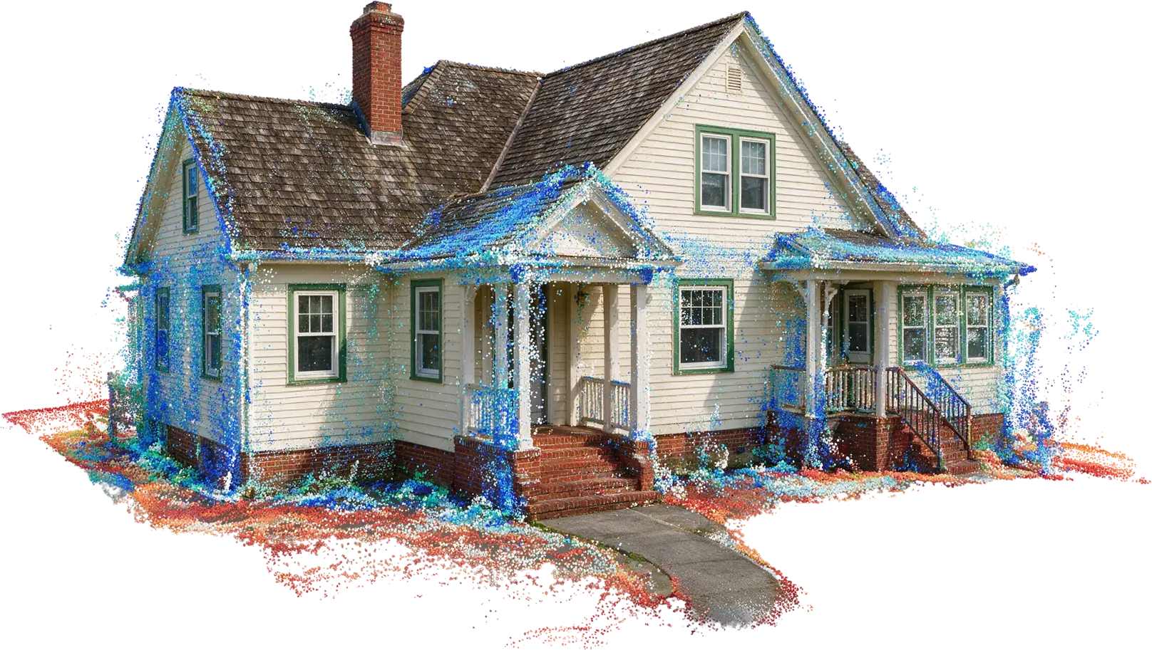
Scan to BIM is the process of converting 3D laser scan (point cloud) data into a Building Information Model (BIM) of existing building conditions, used for design, renovation, and facility management. A laser scanner set up at several positions records millions of measured points. The scans are then registered into one aligned point cloud, and our modelers rebuild the walls, floors, structure, and MEP systems in Revit for you to measure and design against.
The result is an existing conditions model of the building as it stands today, including the changes the old drawings never recorded. Renovations, extensions, and coordination are more reliable when you plan them against verified geometry.
Everything traces back to the on-site capture, so the quality of the scan and its registration limits how accurate the model can be. We check scan coverage and registration quality before modeling starts, then model to the level of accuracy your project needs. For a cloud that is already registered, see our Point Cloud to BIM service.
Reality capture
Millions of scan points→one coordinated model
What we deliver
What's included in a Scan to BIM model
Every model is built from your registered scan and checked against the point cloud: architecture, structure, and systems modeled to the agreed level of accuracy in a clean, well-organized Revit file.
-
Point Cloud Registration
Raw scans indexed and registered in ReCap into one point cloud, cleaned of noise, and set to project coordinates.
-
Architectural Elements
Walls, floors, ceilings, roofs, stairs, doors, windows, and openings modeled true to the captured geometry.
-
Structural Framing
Columns, beams, slabs, and framing modeled where the scan captures them for renovation and analysis.
-
MEP Systems
Ducts, pipes, conduit, and equipment modeled to support coordination and clash reviews.
-
Levels & Grids
Levels and grids matched to the scan, with shared coordinates so the model links cleanly with new design work.
-
Existing Conditions Sheets
Plans, elevations, and sections generated from the model for your as-built documentation.
-
Coordinated Deliverables
Native RVT plus IFC, DWG, or NWC exports, built to your template, worksets, and naming standards.
How accurate is the model
Scan to BIM level of accuracy (LOA)
Not every project needs a millimeter-perfect model. We work to the USIBD Level of Accuracy (LOA) specification, which defines tolerance bands at 95% confidence, and match the band to your scan quality and how the model will be used.
LOA 20approx. 15 mm
Planning-grade existing conditions
Elements sit in the right place at the right size, built from typical wall and floor assemblies rather than modeled face by face. This tier suits layout work and area checks.
-
Typical use
-
Early feasibility, space planning, and concept design where general geometry is enough.
Most common
LOA 30approx. 6 mm
Design-grade existing conditions
Each modeled surface is fit to the registered scan, so wall thicknesses, heights, and openings follow the real building. Most renovation and coordination projects ask for this level.
-
Typical use
-
Design development, renovations, and MEP coordination on existing buildings.
LOA 40approx. 1 mm
Precision as-built
Geometry is modeled tightly to high-density scan data, down to fine deviation and detail. We reserve LOA 40 for elements where close-tolerance fit-out or fabrication depends on the numbers.
-
Typical use
-
Prefabrication, tight tolerance fit-out, and critical connection or clash zones.
We agree on the target LOA up front, per scope or even per element, so the stated accuracy matches what the scan supports. One project can mix tiers: a structural core at LOA 40, general architecture at LOA 30, and back-of-house at LOA 20. LOA sets the tolerance; LOD sets how fully each element's geometry and data are developed.
Why it matters
Why is Scan to BIM necessary?
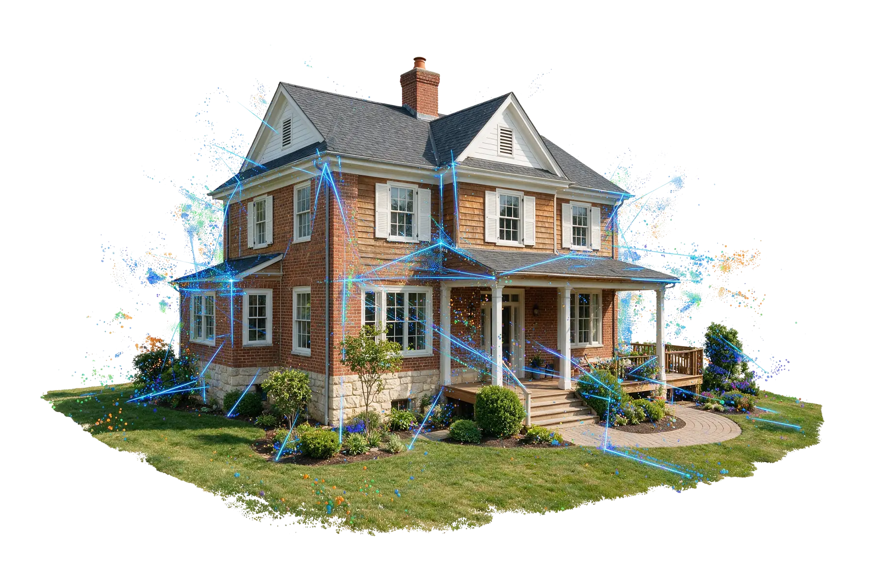
Existing buildings rarely match their old drawings. Decades of undocumented changes relocate walls and swap out systems, and many older structures have irregular geometry no drawing set records. Renovations designed from those documents run into surprises on site. Scan to BIM replaces them with a measured model of what is there.
Starting from verified geometry puts every team on the same baseline. You make fewer site visits, and fewer clashes turn into rework once construction begins.
-
It captures the building as it stands today, so design decisions rest on measured conditions.
-
Clashes between new work and existing framing or ductwork show up early, before they become field problems.
-
Every discipline designs and details against one coordinated existing conditions model.
-
Teams take new measurements from the point cloud at their desks instead of sending someone back to the site.
-
Renovation and retrofit teams confirm structure and services in the model before work starts.
-
After handover, the owner keeps the model as a record for running the building and planning later work.
Where it applies
Industries We Serve
-
01
Architects & Design Firms
Reliable existing conditions models, so your renovation and extension design starts from measured geometry.
-
02
Structural & MEP Engineers
Accurate as-built framing and services to analyze, retrofit, and coordinate around.
-
03
General Contractors
Verified site geometry that de-risks renovation, fit-out, and prefabrication before work begins.
-
04
Facility & Asset Owners
A record model of the building for facility management, maintenance planning, and future projects.
-
05
Heritage & Restoration
Detailed models of historic fabric, with measurements and profiles taken from the scan.
-
06
Industrial Facilities
Congested process areas, piping, and equipment modeled from scan data for retrofit and clash coordination.
-
07
Surveying & Reality Capture Firms
Modeling capacity that turns your captured point clouds into finished, coordinated BIM.
How it works
Our Scan to BIM Process
01
Scope & Target LOA
We review your scans and existing drawings, then agree on the elements to model, the target LOA, and your Revit standards.
02
Register the Scan
We align the scans in ReCap, clean out noise, and set the indexed point cloud to project coordinates.
03
Model to the Cloud
We rebuild architecture, structure, and systems fit to the scan at the agreed tolerance.
04
Verify Against the Cloud
We check every element back against the scan and against its LOA target.
05
Deliver & Support
We issue the Revit model and exports, and support your team through any revisions.
Why Arcengine
Why Choose Us
Point Cloud Specialists
A team that works in point clouds daily, from registration through finished Revit modeling.
Checked Before Delivery
Each model is reviewed for fit to the cloud, completeness, coordination, and naming before it leaves us.
Registration Done Right
Careful scan alignment and coordinate control, because the model can only be as accurate as the scan behind it.
Works to Your Standards
Your Revit template, worksets, and naming rules, followed exactly.
Scales With Your Project
From one room to a multi-building site, our 70+ CAD drafters, detailers, and BIM modelers work to your deadline.
Confidential & Secure
Your scan data, point clouds, and models kept private. We sign NDAs on request.
Explore more
Our Other Services
FAQs
Frequently Asked Questions
Scan to BIM is the process of converting 3D laser scan data of an existing building or site into a Building Information Model (BIM), usually in Revit. The registered point cloud becomes walls, floors, structure, and MEP systems you can measure, coordinate, and design against.
Send your raw scans, or a registered point cloud in a format such as E57, RCP/RCS, PTS, or LAS/LAZ, plus the target level of accuracy, the elements to model, and your project template or standards. We register raw scans ourselves. If you do not have a scan yet, we can advise on capture coverage.
We model to the USIBD Level of Accuracy (LOA) specification, usually LOA 20 (15-50 mm), LOA 30 (5-15 mm), or LOA 40 (1-5 mm). The right tier depends on scan quality, element type, and how the model will be used, and we set it with you for each scope before modeling starts.
We model in Autodesk Revit and use Autodesk ReCap to index and register scans, with Navisworks for coordination when your workflow calls for it. You receive the native RVT model plus IFC, DWG, or NWC exports, built to your template, worksets, and naming standards.
LOA (Level of Accuracy) sets how closely the model must match the scanned surfaces, as a USIBD tolerance band such as LOA 30 (5-15 mm). LOD (Level of Development) sets how fully each element's geometry and data are developed, per the BIMForum LOD Specification. A Scan to BIM scope needs both, and we agree them per element before modeling starts.
Yes. Where the scan captures them, we model structural framing and MEP systems such as ducts, pipes, conduit, and equipment, so the existing conditions model supports renovation, coordination, and clash reviews. Concealed elements, such as foundations or services inside walls, do not show in a scan, so they can only be modeled from drawings or site notes.
We split large or multi-building captures into zones or levels and register them to one shared coordinate system. Each zone or building is modeled in its own linked Revit file, which keeps file sizes workable and lets several modelers work in parallel on one coordinated set.
Yes. We'll sign an NDA before you share files. Your scan data, point clouds, and models stay confidential through to final delivery, and nothing from your project is shared outside the engagement.
Get in touch
From point cloud to Revit model
Send your scans, raw or registered, or tell us about your site. We will confirm the scope and target level of accuracy, give you a fixed-price quote, and return an existing conditions model in RVT, IFC, DWG, or NWC.