
Structural Detailing
Steel Fabrication Shop Drawings
Assembly and single-part drawings, anchor bolt plans, erection drawings, bolt and material lists, and CNC files, all detailed from one model, so your shop cuts, drills, and welds from the same data.
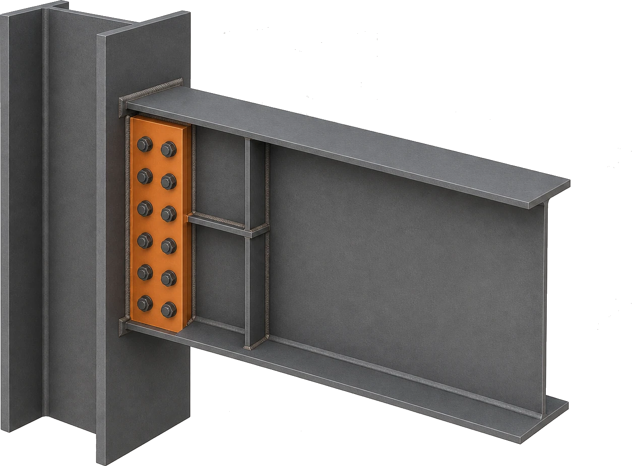
Overview
What are Steel Fabrication Shop Drawings?
Fabrication drawings translate design drawings, which show what the frame has to do, into instructions for making every piece: exact lengths, hole positions, weld sizes, bevels, copes, camber, and the finish each member gets before it leaves the shop. We detail structural steel, sheet metal, architectural steelwork, handrails, and stair systems to your project specifications and the applicable codes.
The frame is modeled once, and the drawings, material lists, and machine files are all generated from that single model. As a result, a part drawing, its assembly drawing, and the bill of materials stay in agreement, and an error caught in the model is fixed everywhere at the same time.
The shop needs drawings it can cut and fit from without asking questions. The erector needs plans and marks that show where each finished piece lands on site. We prepare both, to your piece marking rules and your fabrication standards.
At a glance
-
Modeled in
-
Tekla Structures · SDS2
-
Best for
-
Fabricators & steel erectors
-
Covers
-
Assembly, single-part & erection
-
Delivery
-
DWG · PDF · DXF · CNC/DSTV
-
Detailed to
-
AISC & your shop conventions
What we deliver
What's included in a Steel Detailing Package
Everything is generated from one checked detailing model, so the drawings on the shop floor, the lists in purchasing, and the files on the machines all describe the same steel.
-
3D Detailing Model
The full frame modeled with every member, plate, bolt, and weld, checked for fit before any drawing is issued.
-
Assembly Drawings
One sheet per main member showing the attached plates, clips, and stiffeners with fit-up dimensions.
-
Single-Part Drawings
Every loose plate, angle, gusset, and cut member drawn with holes, bevels, and edge preparation.
-
Connection Details
Shear tabs, moment connections, base plates, splices, and braces detailed to the engineer's design or criteria.
-
Material and Bolt Lists
Grade, size, length, and quantity for every piece, with bolt lists split by assembly and by shipment.
-
Erection Drawings
Framing plans, elevations, and section marks that show the crew exactly where each piece mark lands.
-
CNC and DSTV Files
Machine-ready part files exported from the model for beam lines, drills, and cutting equipment.
Inside the submittal
What lands in a fabrication package
A steel submittal holds six different outputs, each made for a different job and picked up by a different person or machine.
Assembly Drawings
One drawing per main member: the beam or column with every plate, clip, and stiffener welded to it, dimensioned for fit-up.
Used forThe fitter lays out and welds the shipping piece from this sheet.
Single-Part Drawings
Every loose piece drawn on its own: plates, gussets, angles, and cut members with hole positions, bevels, and edge preparation.
Used forCutting, drilling, and coping the individual part before it reaches the fit-up bay.
Anchor Bolt and Setting Plans
Anchor bolt layouts tied to the building grid, with projections, embedment, base plate sizes, and leveling data.
Used forThe concrete crew sets the bolts before any steel arrives on site.
Erection Drawings
Framing plans, elevations, and details showing where each piece mark goes, with field bolts and field welds called out.
Used forThe erector sequences the lift and connects the frame in the right order.
Bolt and Material Lists
A bill of materials with grade, section, length, and quantity for every piece, plus bolt lists grouped by assembly and by load.
Used forPurchasing orders material and the shop stages the right bolts per shipment.
CNC and DSTV Files
Machine-readable part geometry exported straight from the detailing model, one file per part.
Used forBeam lines, drills, and plasma or saw equipment run without re-keying dimensions.
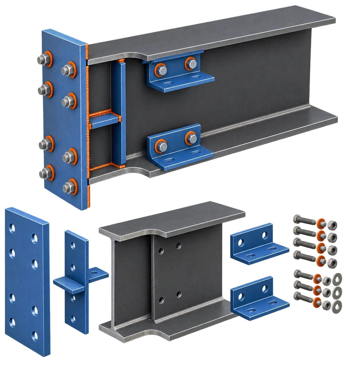
Why it matters
Why are shop drawings necessary?
An engineer's design drawing shows intent. It says this beam carries this load and connects here. It does not say the plate is 12 mm thick, the holes sit 70 mm from the edge, and the member ships at 8,412 mm with a 15 degree bevel on one end. Somebody has to work that out before steel is cut, and shop drawings are where that work is recorded and checked.
Steel is unforgiving once it is cut. A hole in the wrong place means a piece comes back off the truck, and the erection sequence stalls behind it. Detailing is the stage where those mistakes are cheap to fix.
-
They translate design intent into buildable geometry: exact lengths, holes, welds, bevels, and camber the shop can work to.
-
Clashes, short members, and missing plates surface in the model instead of on the shop floor, where a fix costs real money.
-
Piece marks give every part a single identity that follows it through fabrication, painting, shipping, and erection.
-
Material lists come straight from the model, so tonnage, bolt counts, and purchase orders match what will be built.
-
The submittal gives the engineer of record a reviewable record that fabrication matches the approved design.
-
Shipping and erection sequences can be planned around real assemblies and real weights rather than estimates.
Where it applies
Industries We Serve
-
01
Steel Fabricators
Detailing capacity that scales with your backlog, issued to your marking system and machine formats.
-
02
Erectors and Steel Contractors
Erection plans, field bolt lists, and sequencing marks that keep the crane crew moving.
-
03
Structural Engineers
Submittal-ready packages prepared against your design drawings and connection criteria for review.
-
04
Commercial and Industrial Buildings
Framed structures, mezzanines, canopies, and platforms detailed for shop production.
-
05
Warehouses and Pre-Engineered Buildings
Portal frames, purlins, girts, and bracing detailed for repeat-bay fabrication.
-
06
Plant and Process Facilities
Pipe supports, access platforms, stairs, handrails, and equipment structures.
-
07
Miscellaneous and Architectural Metals
Stairs, railings, ladders, gratings, and secondary steel packages detailed alongside the main frame.
How it works
Our End-to-End Process
01
Set the Standards
We agree on the connection criteria, piece marking rules, bolt and weld conventions, and shipping limits up front.
02
Build the Model
The frame is modeled member by member with plates, bolts, and welds resolved in three dimensions.
03
Produce the Drawings
Assembly sheets, part drawings, erection plans, and material lists are generated from the checked model.
04
Check Before Issue
We check dimensions, marks, quantities, and clashes against the design drawings and your standards.
05
Issue and Revise
We release the submittal with CNC files, then fold approval comments back into the model and reissue.
Why Arcengine
Why Choose Us
Detailing Software Fluency
We detail in the industry-standard tools: Tekla Structures, SDS2, AutoCAD, and Advance Steel.
Built for the Shop Floor
Drawings and CNC output set up for how your fabrication line runs and the formats it works from.
Your Standards, Followed
Your piece marking, sheet numbering, title blocks, and bolt and weld conventions, applied exactly.
Checked Before Issue
Every assembly, part, and material list is reviewed against the design drawings before it leaves us.
Clean Revision Control
Approval comments go back through the model, so drawings, lists, and machine files stay in step.
Confidential & Secure
Your models, drawings, and project data handled securely and privately.
Explore more
Our Other Services
FAQs
Frequently Asked Questions
A full package usually carries assembly drawings for each main member, single-part drawings for every loose piece, anchor bolt and setting plans, erection drawings, bolt and material lists, and CNC files for the shop machines. The mix depends on what your shop and erector work from.
A shop drawing tells the fabricator how to build one piece: dimensions, holes, welds, and cuts. An erection drawing tells the crew on site where each finished piece goes, with piece marks, grid lines, elevations, and field connection details.
Send the structural drawings and specification, the connection design or the engineer's connection criteria, your piece mark and numbering rules, and any shop preferences on bolt types, weld standards, and shipping limits.
We work in industry-standard tools including Tekla Structures, SDS2, AutoCAD, and Advance Steel. The model and drawings are set up so the output matches the way your shop already works.
Yes. We export CNC and DSTV files from the detailing model so beam lines, drills, and plasma or saw equipment can run directly from the part data instead of re-keyed dimensions.
We detail connections to the design shown or to written criteria supplied by the engineer of record. Connection design and approval stay with your engineer of record.
Yes. The package is issued to your title blocks, piece mark logic, sheet numbering, and drawing standards. A sample assembly and part drawing is approved before full production.
We bring review comments back into the model, so the assembly drawings, part drawings, material lists, and CNC output are all reissued in step, with a clear revision record.
Get in touch
Shop-ready, not just drawn
Send your structural drawings, specification, and connection criteria. We will confirm your marking and standards, then return assembly drawings, part drawings, erection plans, material lists, and CNC files ready for the shop floor.